Designing the UI-The colour scheme

For the past while my focus has shifted to work on the UI while my co-worker works on the shader file.

The first issue I came up with was what colours to use for the UI. So this is a short post on my thought process behind picking colours.

Even though blues are a popular choice for UI I wanted to use a different colour scheme. I started by taking inspiration from the colours commonly found in cameras. The colours I found in a lot of different cameras where blacks, dark greys and silvers. For the UI I liked the idea of using sliver so I found a nice sleek sliver tone I liked #D7DBE1 and then created the UI with that.

For the splash screen it was stated that a blackish background with light font was wanted so I went from there. I know that straight black and white is too harsh/jarring for users to see so I went with a dark grey for the background and light grey for the font. The background grey I used #2D2F31, my hope with this colour is that it reminds someone of the colour of the body of a camera ( a really dark grey). The colour I used for font was #DCD8D6 to find this one I went online and looked for what light greys would go good with the dark grey I used as the background.

The only other to mention in terms of design for the UI is the font. In order to find this I went on bootstrap theme pages and design websites and found a sleek typography that I thought suited the UI. One such that I liked was the Comso theme on bootswatch. This theme used the Source Sans Pro font found on google fonts.

That’s it mostly for the design concepts that went into the UI. Next up I will talk about the scripting behind the UI.

Cheers,

Barbara

Callback hell and promises

While creating the GUI for my project I ran into a tiny bit of a callback hell, so I will talk a little about promises and how they are useful.

While making the GUI I used jQuery for to populate the camera and lenses select boxes. The main thing about jQuery that is important for this post is that it is async; this means that the rest of the code block will run while the jQuery request is being made. In my code I have the select boxes populate and change appropriately, in order to do this I needed to use callbacks to manage this async nature.

This lead to callback hell where my callbacks needed to be nested and I ended up with the “triangle of doom.” Callback hell is suck a widely know occurrence with async javascript that there is even a website devoted just to callback hell.

There was two things I did to clean up the code a bit which included promises and making modules.

First a bit about promises. There is a really good webpage that a coworker directed me to that I will post here.   It’s worth pointing out that jQuery actually has “Deferreds” these are actually a little different than promises but there is a way to cast to javascript promises with;

var thisPromise = Promise.resolve($.ajax('jsonFile.json'));

You can go to jQuery’s website to view more about Deferreds and how they can be used. For promises they can be chained together to make a sort of queue that the statements run in. This can be done with .then, I will so an basic example to make it easier to understand.

yourasynccall('jsonfile.json)
.then(function(data0) {
  //do what you want here
  return anotherasycncall(data0);
})
.then(function(data1) {
  //do more
  //can return a third async call here
})
.catch(function(err){
  //catch any error that occured
});

The second thing that I did to make the code easier to read is to modularize the two parts that are async. Basically what was done is have lens and camera select separate modules

privateMethods.LensSelect = function (lensfolder) { 
//the async code here with promises 
};

And then in the method where the GUI is being made call the above method like so

var lensfolder = this.gui.addFolder("Lens");
 privateMethods.LensSelect.call(this, lensfolder);

Using these two concepts; promises and modules my code has less chance of being spaghettied.

For the future the GUI is going to made in a different way using bootstrap so look forward to that.

Cheers,

Barbara

A short post on debugging three.js shaders

Just a very small update on how it was to create the shader I made before and how I went about debugging it.

Debugging shaders is known to be very hard and there are a couple of ways to debug your code. The first way is to set your values to a gl_fragcolor and compare the output of your texture with the values you want.

There is some software that people have released in order to debug webgl that I didn’t use but may be useful for some people. One of them being Web Gl inspector. As well there is a Firefox Web Gl shader edition This allows you to edit the shader code in realtime and mouse over to see it’s effect in the scene. And if you prefer chrome there is a some Chrome canvas inspection dev tools that allow you to capture frames and debug code as well.

Of course if you don’t feel like downloading something or using a different browser you could do some rubber duck debugging but I would strongly recommend using the programs or techniques above.

That’s all for now, stay tuned for a brief post on promises.

Cheers,

Barb

The thrilling saga on shaders continues

In my last post I detailed some basics of creating a shader and in this post I will be focusing on how to create a depth of field shader.

There is going to be a couple files that need changing including the shader file and the main js file. I am going to start off with the shader file and mention the js file later.

As I stated before in the last post the depth of field shader is only going to change the fragment shader so the vertex shader will be the same as the one that I have posted on the last post.

So this post will manly focus on the fragment shader. I was going to talk about the code in the shader but that has made the post too long so I will talk about the main concept of creating depth of field. Which is as follows; create a texture containing the depth map. Then grab the value from the depth texture to figure out how far away from the camera the pixel is. Using the inputs from the camera find out what the near and far depth of field areas are. We can then compare the depth of pixel to the near and far depth of field to find out how blurry it should be. We then do something called image convolution. This process grabs the colour of the pixels around the certain pixel and adds them together so that the final pixel is a mix of all the colours around it.

To get the shader to work Three.js has something called effect composer and shader pass to work with your shaders. This is done in rough form as follows;

composer = new THREE.EffectComposer( renderer );
composer.addPass( new THREE.RenderPass( scene, camera ) );

var Effect1 = new THREE.ShaderPass( shadername, textureID );
Effect1.uniforms[ 'value1' ].value = 2.0 ;
Effect1.renderToScreen = true; //the last shader pass you make needs to say rendertoscreen = true
composer.addPass( Effect1 );

Then to get this to work you need to call composer.render() in the render loop instead of the normal renderer.render().

I will end here for this post, If need be I will wrap up some minor things about shaders in the next post. As well once the scene is nicely set up and the GUI works with real world cameras/lenses I will post a post with a survey to see what shader produces the best results and where it can be improved.

Cheers,

Barbara

An Introduction to shaders

For our project we are using shaders to replicate the depth of field for the camera. The shaders online certainly work but I was not happy with the lack of explanation or the procedure within those shaders, so I have decided to make my own to replicate depth of field.

Within this post I am just going to explain some introductory concepts about using shaders in Three.js and led up to the final shader results in the later posts.

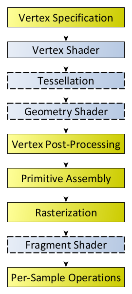
Before going into details about the shaders I am going to talk a bit about the rendering pipeline and then jump back. The rendering pipeline is the steps that OpenGL (The API that renders 2D and 3D vector graphics) takes when when rendering objects to the screen.

RenderingPipeline

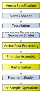
This image was taken from the OpenGl rendering pipeline page here.

Glossing over some things a bit, there is basically two things happening. First the pipeline deals with the vertex data. Then the vertex shader is responsible for turning those 3D vertices into a 2D coordinate position for your screen(responsible for where objects get located on the screen). After some other stuff rasterization occurs which makes fragments(triangles) from these vertices points. After this occurs the fragment shader occurs. This fragment shader is responsible for what colour the fragment/pixel on screen has.

This whole pipeline runs on the GPU and the only two parts of this pipeline that are programmable by a user are the vertex shader and the fragment shader. Using these two shaders we can greatly alter the output on the screen.

For Three.js/WebGL the shaders are written in GLSL (with three.js simplifying things for us a little bit) which is similar to C. This shader file can be separated into three main parts: uniforms, vertex shader, and the fragment shader.

For the first part the uniforms this is going to be all the values passed from the main JS file. I’ll talk about passing in values in a later post. A basic example is;

uniforms: {
"tDiffuse": { type: "t", value: null },
"value1": { type: "f", value: 1.2 }
},

tDiffuse is the texture that was passed from the pervious shader and this name is always the same for three.js. The types that can occur in the uniforms are many but some of the basic ones are i = integer, f=float, c=colour, t=texture, v2 = vector2 (also 3 and 4 exist), m4 = matrix4 etc….

The next part is the vertex shader, because of what I want to do (change the colour of the pixel to create a blurring effect) I don’t need to change anything in here, but it is still required to write this in the shader file. If you want to code one you must code the other as well.

vertexShader: [

  "varying vec2 vUv;",
 
  "void main() {",
    "vUv = uv;",
    "gl_Position = projectionMatrix * modelViewMatrix * vec4( positio       n, 1.0 );",
  "}"

 ].join("\n"),

Varying meaning that the value change for each pixel being processed. In this one we have vUv which is a vector that holds the UV (screen co-ordinates) of the pixel and is automatically passed in by three.js. The next line just takes the 3D coords and projects them onto the 2D coords on your screen. I am going to skip the explanation of why this works as it is not important, just look it up or ask me if you really want to know.

Now for the important one, the fragment shader;

fragmentShader: [

"uniform sampler2D tDiffuse;",
"varying vec2 vUv;",

"void main() {",
  "vec4 color = texture2D(tDiffuse, vUv);",
  "gl_FragColor = color;",
"}"

].join("\n")

For this vUv is the same as from the vertex shader and tDiffuse is the texture that was passed in (stated as sampler2D here). In this main loop we are grabbing the RGBA value from the passed in texture as coord vUv and then assigning it to the output pixel.

This is the shader I will be using to create a depth of field and for the rest of the posts I will be looking at this shader only.

That’s it for the introduction, next post I will start to get into the fragment shader and image convolution.

Cheers,

-Barbara

What’s in a GUI

In this post I am going to talk about adding a GUI to a test scene so that a user can change values. I have meant to put this up earlier but got side tracked because I was watching  Hannibal’s season 3 premiere which has some of the most breathtaking cinematography I have seen, so if you want just what sort of results a cinematographer can create that would be the show to watch.

So back to the GUI, using THREE.js there is a library file called dat.gui which you can grab from google code page. Within your javascript file you can start making the GUI with;

  var gui = new dat.GUI();

I also recommend creating something to hold all the values that are going to be used in the GUI so in this case

var params ={

format:’16mm’,

focallen: 100,

…(all other camera and lens properties)

};

If after you made the GUI you want to add folders you can add them with;

var camfolder= gui.addFolder(Camera);

var lenfolder=…

After you make all the folders you want you can start adding variables to the folder with;

var foc = lenfolder.add(params, focallen‘); 

The gui.dat library will add text boxes or sliders depending on if the value in params was a text or a number. So for the number values we can change it so that the user has a lower and upper limit for what the value can be and change the increment for the slider with using this line instead;

var foc = lenfolder.add(params, focallen,10,200).step(4).name(focal length);

The other type of input was a select menu for camera/lens. In order to do this the first step is to store the information about the camera/lens into a JSON file. After having the file we can use  jQuery;

$.getJSON(“locationoffile”,function(data){

//the inner working may change depending on how the JSON file was setup but you are          //going to use $.each to loop through the JSON file getting each entity and grab the value you    //want. So for this example I looped and grabbed the format value and then added it to an  //array of cameras(listcams).

after looping with the $.each we can use this list of cameras formats as options for the menu with

var cam = camfolder.add(params,’format’,listcams);

After having the GUI working we want it to do something when we change values so we can use

foc.onChange(function(value){

params.focallen =value;

});

We can do this for all values to continuously update the params. If you are running into issues with the JSON and storing the values gathered from the JSON file just remember that jQuery is async and do the onChange within the $.getJSON above.

If you want to add a button to the GUI the best way to do that is;

var obj= {submit:function(){

//logic that occurs when pressed here

//I did calculations of Hyperfocal distance and depth of field here

}};

gui.add(obj, ‘submit’);

So this is basically all we will need to work with in terms of making and changing the GUI. The next step that my partner and I worked on was the depth of field using shaders. So next blog post I will talk about shaders before going into depth about them with depth of field.

Have a good night everyone.

-Barb


First up a test scene

Most feedback I got from the last post was that it was too mathy and I promise this one will have 100% less math than the last one.

The first thing to do done in the project was to make a test scene to work with. This will allow us to try different techniques and see if the outcome was expected.

The first part of making the test scene was to make walls and a ground. By using the box geometry or plane geometry in THREE.js is it very easy to make a wall or ground of size wanted. Adding all walls and the ground to an single object3D object allows us to move the whole scene around if we want the walls and ground to be in a different place.

To help measure units in the scene better a black and white checkerboard pattern was added to the wall and ground. The best way to do this is to have a small texture pattern of the checkerboard and to set texture.wrapS and texture.wrapT to THREE.RepeatWrapping and then use texture.repeat.set(x,x) where x is half the length/width of the geometry used above. Basically these three lines will cause the small checkerboard texture to appear on the whole wall/ground.

After having the basic walls and ground of the scene set up the next part is to add some detailed objects to the scene. Instead of boxes and spheres we need something will more definition and I decided to use humanoid models. There are a couple different ways to add external models to the scene. The way I did was to use MakeHuman software which allows you to easily make models and use them under the cc0 license. Exporting the created model to a obj/mtl files allows easy use in THREE.js. You can also use Clara.io to make a object and export them to the file type you want.

To load the model THREE.js has a obj/mtl loader. The THREE.js website has excellent documentation on how to use it so I will say to check that up if you need to. After the model is loaded you can make as many meshes of the model as you want to put in the scene. The models can be easily scaled for accurate dimensions. By defining 1 THREE.js unit as representing 1 foot we can resize the models. Using a box of dimension 6x2x1 I can resize the human model to fit inside the box and therefore be accurate. I also added all the humans to a single object3D so that all humans can be moved at once. For my scene I ended up putting 5 human models in the scene spaced evenly apart from each other.

With these elements we have a scene that can be customized for any dimensions or distances we may want to test depth of field or field of view.

I was going to talk about adding the GUI here but I think instead I will make a separate post talking about the GUI so I can mention some specific points in creating it. So look forward to that next.

-Barb

Everything you wanted to know about cameras

In this post I will detail the main points related to the image that is produced in a camera.

Without going into too much detail on how cameras and lenses work there are three main things that the final image can differ in:

1) Field of view

The field of view is how much of the area in front of you will be on the final image taken by the camera. While field of view and angle of view tend to be used interchangeably they are different in that field of view refers to the distances in real life that are being placed on the final image angle of view refers to the angle from top to bottom that is extended out from the camera.

To find the angle of view you need to know the focal length of the lens and the size of the film or sensor used in the camera. This following image by Moxfyre at English Wikipedia (under CC BY-SA 3.0) shows the best example for this concept 

Wiki page

Optics of a Camera

In this S1 is the distance from the lens to the object, S2 is the distance from lens to the sensor or film, and F is the focal length of the lens. You can see that as you increase the focal length while keeping the film sized fixed the angle will get smaller. If you keep the focal length the same but increase the film size the angle will get bigger. The equation to find the angle of view is easy enough to find with trigonometry from the above equation (with the assumption that S2=F which is not a valid assumption for macro situations but is valid for distant objects) and is

α = 2*arctan(d/2f)                                                                                                  (1)

The above can be looked at as if top down or from the side, in fact the angle of view tends to be different from horizontal and vertical as the film size is different for these dimensions.

Therefore field of view depends on film/sensor size a property of the camera chosen and focal length which is a property of the lens chosen.

2) Depth of field

Depth of field may be a little harder to understand and refers to the area that will be sharp or acceptably sharp in the final image. The first thing to do to find the hyperfocal distance. This distance is where objects will be in focus from half the hyperfocal distance up to infinity(past the half distance it is always in focus).

For example if the hyperfocal distance is 20m and you decide to focus on an object 25m away then the image will be in focus from 10m to infinity. If you focus on something 15m away(<H) then you have a finite depth of field which you will have to calculate.

First the equation for the hyperfocal distance, at the risk of being too mathy I will leave out the derivation (which can be found with geometry)

H = (F^2)/N*C                                                                                                      (2)

Where F is the focal length, N is the f-stop and C is the circle of confusion. The f-stop is the aperture and is the ratio of focal length to diameter of entrance pupil. C is the circle of confusion which is a property of a lens and is where light will not come to prefect focus.

After finding the hyperfocal distance the near and far depth limits can be found after knowing the focus distance (which is something the cinematographer picks.)

DNear = H*S                                                                                                         (3)             H+(S-F)

DFar = H*S                                                                                                           (4)           H-(S-F)

Where H is the hyperfocal distance and S is the focus distance.

For a good explanation of how depth of focus works go to this page.

Therefore the depth of field depends on focal length which is a property of the lens, circle of confusion which is also a property of the lens, aperture which is a property chosen by user and focus/subject distance which is also chosen by the user.

3) Exposure

This last thing I will mention but not go into detail. This refers to the amount of light going into the camera and how bright the picture will be. This depends on many things like aperture, shutter speed, and lights placed in the scene.

Therefore the main this that a user should be able to pick are the type of camera, type of lens, aperture setting, focus distance, and maybe focal length of lens if it a zoom lens.

Stay tuned for the adventure of making a test scene to use and verify our cameras in.